| Main page |
|
|
|
|

|
| Railways |
| Auto Roads |
| Artificial Structures |
| Hatch |
| Distances To Boundaries |
| Design Data Table |
| Main Site Broadening |
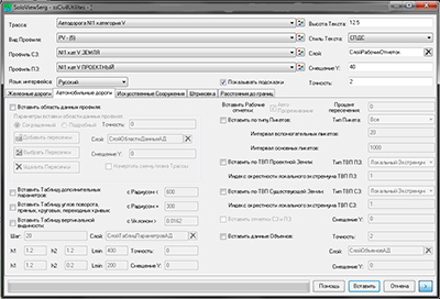
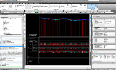
On the tab Auto Roads you can:
Insert the labels of working, existing, project elevations and distances on the profile view taking into account 10 criteria:
enable/disable automatic thinning, select percent of intersection ( the allowable percent of labels intersection);
select insert types of labels of working, existing, project elevations and distances;
press 'Insert'.
Before inserting labels of working, existing, project elevations and distances it is recommended with help of AutoCAD Civil 3D Styles and Labels 2.1 lead the profile view to necessary view( in the example - GOST P 21.1701-97 AR Form 6 (+Detailed alignment plan)), disable the display of the data bands 'Working elevations', 'Alignment axis elevation', 'EG Ground elevation', 'Distance', 'Plane elements', insert Cross lines and fill the data bands 'Detailed alignment plan', 'Plane elements' by GOST. Also on view profile you can insert Artifical Structures labels.
When selecting the insert of labels of working, existing, project elevations and distances is drawn block consisting of a working, existing, project elevations and distance labels.
Insert types of labels of working, existing, project elevations and distances:
by type of station:
All;
Major;
Minor;( A step of major and minor station is defined in the respective input fields.).
GeometryPoint;
Station Equation;
SuperTransPoint;
PIPoint;
M&M( Major&Minor);
M&M&GP( Major&Minor&GeometryPoint);
M&M&GP&STP( Major&Minor&GeometryPoint&SuperTransPoint);
M&M&GP&STP&PIP( Major&Minor&GeometryPoint&SuperTransPoint&PIPoint);
GP&STP&PIP( GeometryPoint&SuperTransPoint);
GP&STP&PIP&Eq( GeometryPoint&SuperTransPoint&Station Equation);
by Finished Ground PVI:
All;
Local extremum;
by Existing Ground PVI:
All;
Local extremum;
The index Area of the search of Local Extremum - number of inquiry PVI near testing PVI.
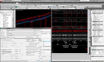
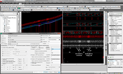
The optimal method of insert labels of working, existing, project elevations and distances:
1. Enable automatic thinning, select percent of the intersection.
2. Insert labels of working, existing, project elevations and distances by All station types, all Finished Ground PVI and all Local extremum of Existing Ground vertical profile.
Notes:
1. Labels of working, existing, project elevations and distances by Finished Ground PVI have the highest status on the criterion of thinning, i.e. not thin( when you select 'FG PVI type'='All' is inserting all labels of working, existing, project elevations and distances by Finished Ground PVI);
2. Insert of distance labels by Finished Ground PVI depends on the choice of the parameter 'Finished Ground PVI Type Local Extremum Area Index':
if parameter=1, then distance labels by Finished Ground PVI is inserted ( As shown on picture 'Labels of working, existing, project elevations and distances with automatic thinning ( including labels of distances by Finished Ground PVI), GOST P 21.1701-97 AR Form 6 (+Detailed alignment plan) profile view').
if parameter=0, then distance labels by Finished Ground PVI is NOT inserted.
The alternate method of insert labels of working, existing, project elevations and distances:
1. Disable automatic thinning.
2. Insert labels of working, existing, project elevations and distances by station type( for example - M&M - Major&Minor) and Local extremums( As shown on picture 'Labels of working, existing, project elevations and distances without automatic thinning').
3. Manually thin out labels of working, existing, project elevations and distances.
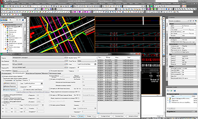
Insert profile view data bands( detailed ( containing bands 'Detailed alignment plan', 'Plane Elements') M1:5000):
select insert of profile view data bands labels( detailed);
press 'Insert'.
Insert at profile view the scheme of alignment plan with cross lines:
select insert of profile view data bands labels;
select insert the scheme of alignment plan (Direct Road Plan);
press 'Insert'.
Add objects crossing by alignment:
press ![]() 'Add Cross Lines' and point start and end of crossings( in current version supported lines only);
'Add Cross Lines' and point start and end of crossings( in current version supported lines only);
return - press 'Esc';
Delete objects crossing by alignment:
select cross line in data view and press ![]() 'Delete Cross Lines' or in context menu of data view 'Delete'.
'Delete Cross Lines' or in context menu of data view 'Delete'.
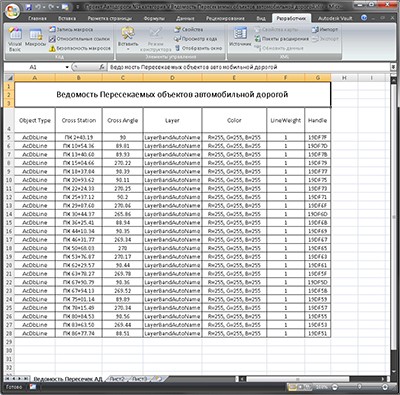
Import table of objects crossing by alignment:
select insert of profile view data bands labels;
select any cell in MS Excel worksheet, which contains bill, formatted and aligned in the Excel worksheet as in the example;
press 'Import from Excel'.
Export table of objects crossing by alignment:
press 'Export in Excel'.
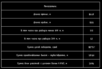
Get Advanced Parameter Table:
select insert Alignment advanced parameter table;
define initial parameters;
press 'Insert'.
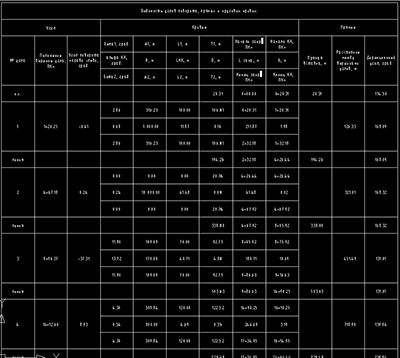
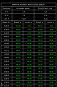
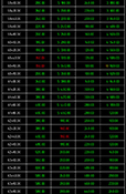
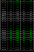
Get Auto Road Plane elements Parameter Table of Rotation Angles, Tangents, Curves, Spirals:
select insert of Auto Road Plane elements Parameter Table of Rotation Angles, Tangents, Curves, Spirals;
press 'Insert'.
 |
 |
 |
Get Visibility Parameter Table:
select insert of visibility parameter table;
define initial parameters;
press 'Insert'.
| Copyright © 2008 - 2024 |